Usb To Network Wiring Diagram. Web ethernet cable wiring diagram with color code for cat5 cat6 etechnog. These include the type of ethernet port, the type of usb port, the type.
Usb To Wiring Schematic from howdoigetboneheadssecurityhoodiem.blogspot.com
Cable matters usb to ethernet adapter 2. Web the usb c wiring diagram below shows the “ usb type c to micro usb 2.0 type cable assembly” diagram: Web understanding wiring diagrams for ethernet usb connections the ability to create a secure and reliable network connection is a must for many businesses today.
Web As Technology Advances, More People Are Turning To Usb To Ethernet Wiring Diagrams To Help Them Determine The Best Way To Connect Their Devices.
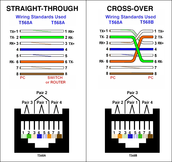
Web with a wiring diagram, you can quickly set up, troubleshoot, and upgrade your network. Web iphone ipad ethernet adapter with power charging lightning to rj45 lan wired network apple otg usb newegg com. Cat 5 wiring diagram crossover cable.
Ethernet Usb Wiring Diagrams Show.
Web the wiring diagram for the usb to ethernet adapter contains a number of different elements. Cable matters usb to ethernet adapter 2. Solder the wires of the usb cables between them.
So, If You’re Looking For A Way To Maximize Your Network Efficiency And.
The timing diagram of the usb protocol is shown below which is mainly used in the engineering field to explain the on/off values of usb wires. Solved access the console using rj45 to usb adapter cisco community. Web a usb to serial adapter wiring diagram is a diagram that shows the connections necessary to make a connection between two devices that utilize a usb.
Web The Usb C Wiring Diagram Below Shows The “ Usb Type C To Micro Usb 2.0 Type Cable Assembly” Diagram:
The wiring diagram for each type of connection will vary. Three conductors and a shield are required for rs485 to work. Usb charging cable and usb otg cable have the same cable.
Web Ethernet Cable Wiring Diagram With Color Code For Cat5 Cat6 Etechnog.
Web the most important part of the wiring diagram is the logical connection, as this determines how the network will function. The first step is very simple, once you connect the cable computers immediately detect the connection of new hardware and install necessary drivers. The rj45 connector has a total of 8 pins and eight colored wires.